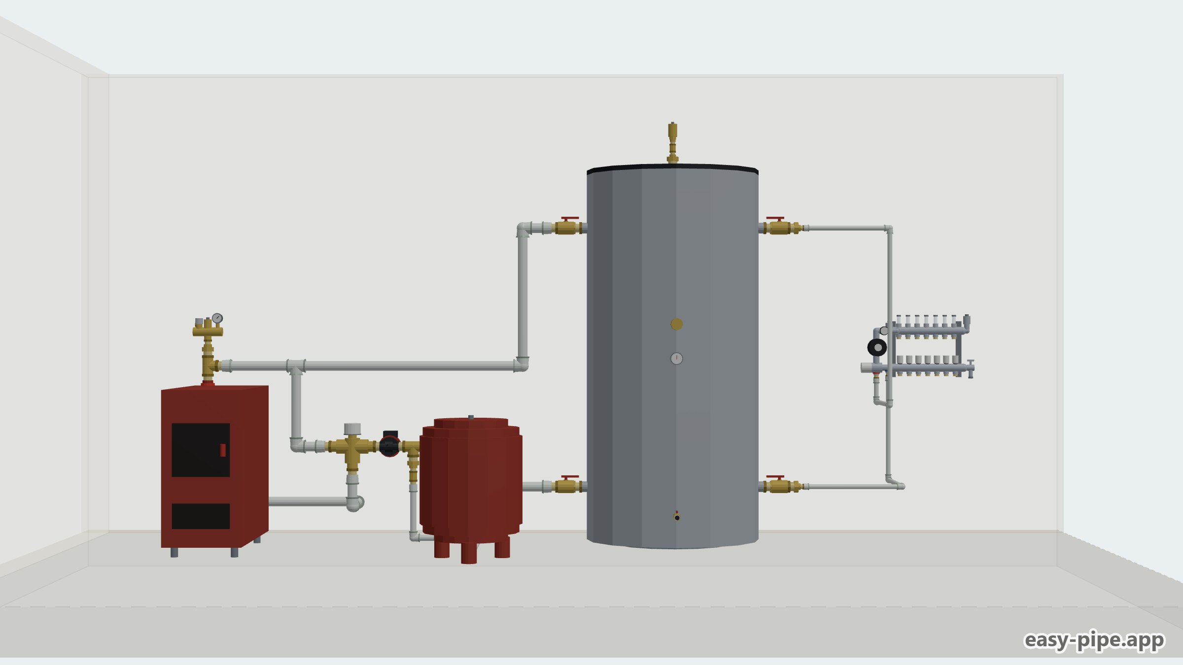
What this scheme does
A solid fuel boiler piping diagram with a buffer tank solves the main contradiction of such a boiler room: the boiler reaches its highest efficiency when running at almost full output, while wet underfloor heating is low-temperature heating and simply cannot absorb that much heat at once. The wood-fired boiler burns a full load and passes the heat into the 1000 l buffer tank, and water at the required temperature is then fed from the tank to the underfloor heating manifold. This way the boiler does not smoulder under part load, and the house keeps getting heat even after the wood has burned out.
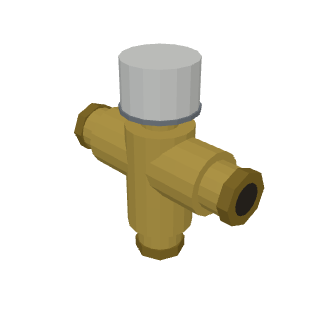
At the boiler outlet there is an anti-condensation valve with a small mixing loop from the boiler return. While the water in the boiler is still cold, the valve circulates it around the short ring boiler — pump — boiler, and the return into the boiler stays warm. This eliminates condensation on the firebox walls, noticeably reduces soot and tar build-up, raises efficiency and extends the boiler's service life. As the temperature rises, the valve opens the way to the buffer tank.
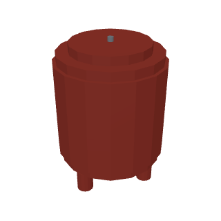
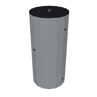
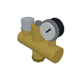
The system is of the sealed type, so an expansion vessel and a safety group with a pressure relief valve and a gauge are mandatory, plus automatic air vents at the high points. The expansion vessel volume is calculated from the total water content of the system: the underfloor loops together with the contents of the buffer tank. Filling and draining are arranged at the bottom of the buffer tank — a convenient place to drain the water before repairs. The tank allows an immersion heater to be fitted: the solid fuel boiler can be shut down and the tank heated electrically, with the heater output chosen to suit the house.
The pipe from the boiler to the buffer tank is never reduced — its diameter matches the boiler and tank connections, otherwise heat removal from the firebox suffers. The section from the tank to the underfloor manifold, however, can be reduced to the size of the manifold inlets, since it has its own pump there and a lower flow rate. In total the diagram has two full independent circuits — boiler/buffer and underfloor heating — plus the small anti-condensation return loop. In the easy-pipe configurator you can change the boiler output, the buffer and expansion vessel volumes, the number of underfloor loops and the pipe diameters to suit your own house; in this version the 16 kW boiler and 1000 l tank are sized for a house of 100–150 m², but equipment should properly be selected according to the building's heat losses.
Scheme specifications
- System type
- Sealed, two independent circuits + small anti-condensation loop
- Heat source
- Solid fuel boiler 16 kW
- Buffer tank
- 1000 l, with the option of an immersion heater
- Boiler protection
- Anti-condensation valve with mixing into the return
- Expansion vessel
- Volume based on total water content: underfloor loops + buffer
- Suitable for a house of
- 100–150 m² when sized by heat losses
Parts in the scheme
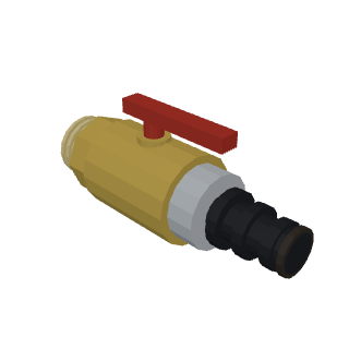
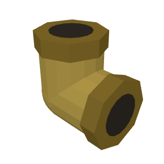
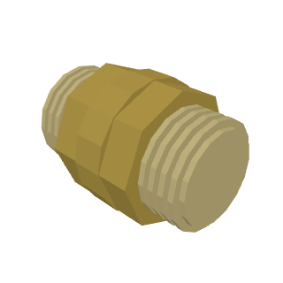
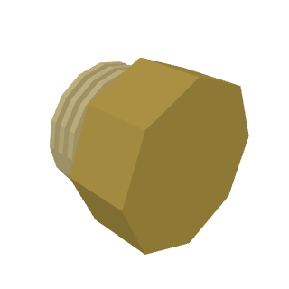
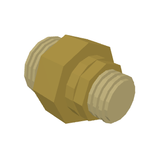
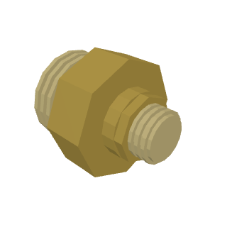
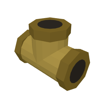
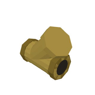
How it was assembled, step by step
Installing the boiler and piping the anti-condensation valve
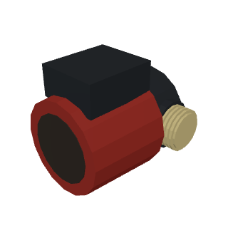
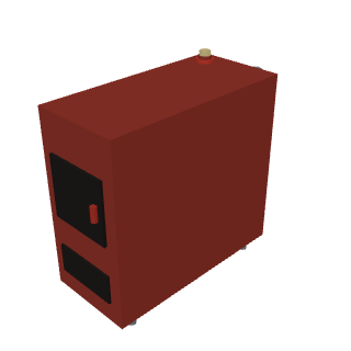
The boiler is placed on a prepared base and connected to the flue. On the flow side, assemble the unit with the anti-condensation valve and the small-loop circulation pump so that the return comes back into the boiler warm. The diameters of this section follow the boiler connections, with no reductions.
Connecting the 1000 l buffer tank
The buffer tank is installed next to the boiler and linked to it by full-diameter flow and return pipes. The top connection is the hot flow from the boiler, the lower one the return of cooled water. At the bottom of the tank, bring out a cock for filling and draining the system; an immersion heater can be fitted into the threaded socket if needed.
Safety group, expansion vessel and air removal
A safety group with a pressure relief valve, a gauge and an automatic air vent is fitted on the boiler flow. The expansion vessel of the sealed system is connected on the return; its volume is chosen from the total water content of the underfloor loops and the buffer. Air vents are fitted at the high points of the circuits.
Wet underfloor heating circuit
A separate circuit runs from the buffer tank to the underfloor heating manifold with its own pump and mixing unit. The pipe diameter on this section can be reduced to the size of the manifold inlets. The floor loops are distributed between the rooms and balanced with the flow meters on the manifold.
Filling, pressure testing and start-up
The system is filled from the bottom of the buffer tank, pushing the air out through the air vents and the cocks on the manifold. Carry out a pressure test, check the pressure on the gauge and the tightness of the joints. During the first firing, watch the anti-condensation valve: the return into the boiler must warm up before heat goes into the buffer.
Video and animation
Frequently asked questions
Can underfloor heating be connected to a solid fuel boiler without a buffer tank?
Wet underfloor heating is a low-temperature circuit that absorbs little heat, while a solid fuel boiler is designed to run at almost full output. Without a buffer the boiler will constantly either overheat or smoulder, with soot and tar in the firebox. The buffer tank takes all the heat of the fuel load and releases it to the floors in portions, so in this diagram it is essential.
Why is an anti-condensation valve needed?
It keeps the boiler return temperature at a safe level by mixing in hot water from the flow through the small loop. A warm return prevents condensation on the firebox walls, which is what causes soot and tar. This raises the boiler's efficiency and extends its service life.
How is the expansion vessel volume calculated?
The volume is based on the total amount of water in the sealed system — add up the water in the underfloor loops, in the pipes and in the buffer tank. The larger the buffer, the bigger the expansion vessel needs to be. In the easy-pipe configurator the vessel volume can be changed to suit your own system.
Can the buffer tank be heated electrically?
Yes, the tank in this diagram accepts an immersion heater in its lower part. The solid fuel boiler can then be left unfired: the tank is heated by the element and the underfloor heating runs off the buffer as usual. The heater output is chosen to match the house's heat losses and the permissible load on the electrical supply.
Why can't the pipe from the boiler to the buffer be reduced, while the one to the underfloor heating can?
The boiler — buffer section carries the full output of the firebox, and its diameter is set by the boiler and tank connections: a reduction would limit heat removal and lead to overheating. The underfloor circuit runs off its own pump at a lower flow rate and low temperature, so the pipe to the manifold may be reduced to the diameter of the manifold inlets.
What size of house is the 16 kW boiler with a 1000 l buffer intended for?
Such a combination usually covers a house of 100–150 m². But the correct way to size the boiler output and the buffer volume is by calculating the building's heat losses: insulation, window area and climate matter far more than square metres.