What this scheme does
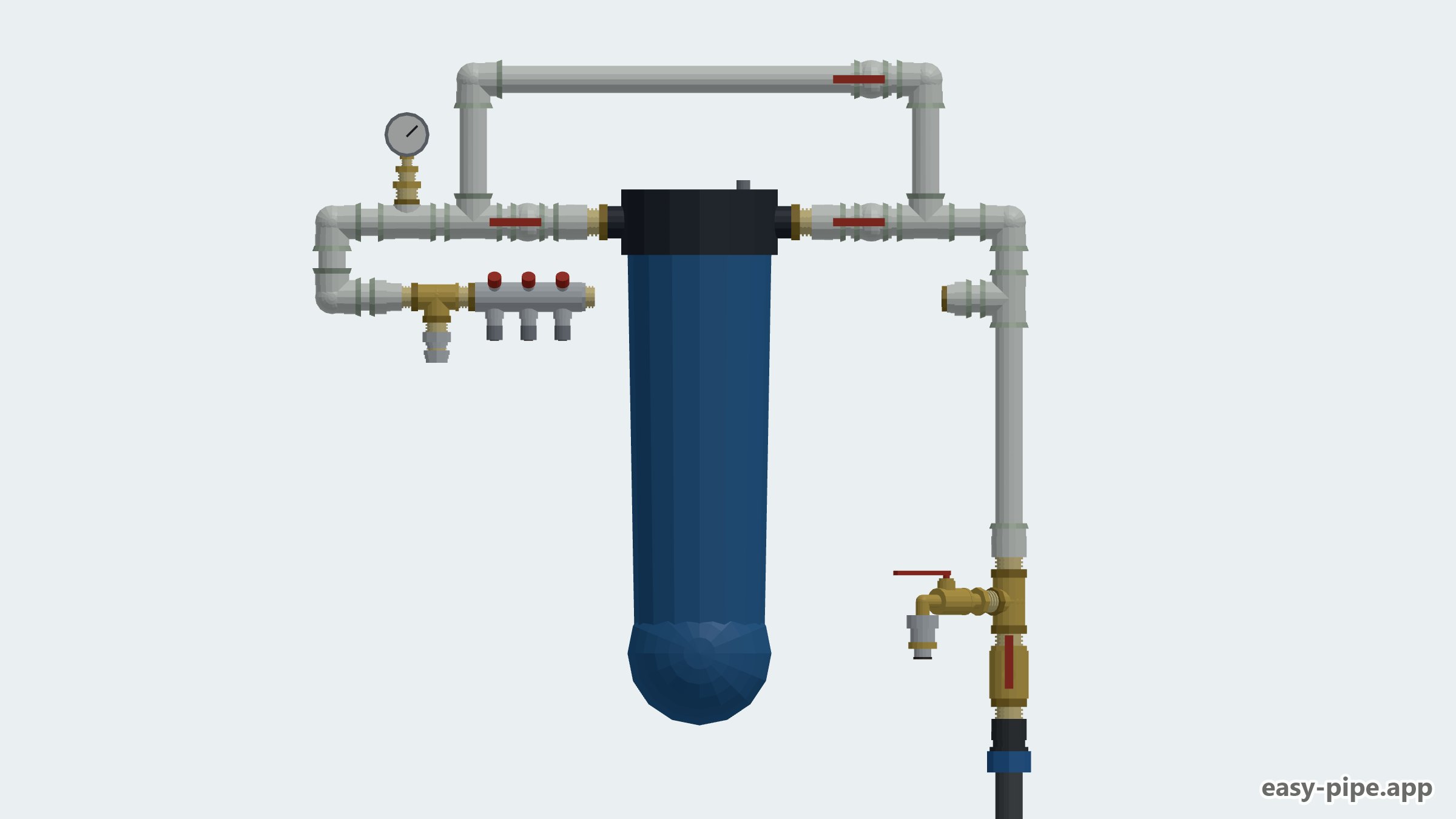
Here the water supply from the well into the house is run in Ø32 HDPE pipe: it comes through the wall, turns with two elbows and, via a compression-to-thread adapter, lands on a brass master valve that shuts off the whole house. Next to it, a brass assembly carries two functions: a drain point for emptying the system and an outdoor take-off with a garden valve fitted with a quick coupling. Both take-offs sit ahead of the water treatment, so water for the beds and for washing the car does not pass through the cartridge.
From there the flow moves onto Ø32 polypropylene and goes to the BB20 mains housing with a carbon cartridge. The one-inch bore is kept along the whole main line — there are no reductions before or after the housing, so the filter does not choke the flow when several points draw at once. The housing is piped with three ball valves: two shut-off valves and one on the bypass leg, so the sump can be removed without stopping the supply. On the outlet, a tee with a threaded branch takes a pressure gauge — it shows the working pressure and the moment when the cartridge resistance has risen.
On the clean side the distribution splits in two: a separate Ø20 line to the water heater through a compression coupling, and a 3/4" mini manifold with three Ø16 outlets on valves — kitchen, bathroom and the second bathroom with the laundry, each branch shut off individually. This set is sized for a holiday-type house of about 100 m² and three residents. In the configurator you can change the number and diameter of the manifold branches, add a second stage of mechanical filtration ahead of the carbon, move the garden take-off or add a valve on the water heater line.
Scheme specifications
- Source and entry
- Well, Ø32 HDPE pipe
- Main line in the house
- Ø32 PPR (1") up to the manifold
- Shut-off at the entry
- 1" master valve, drain valve
- Filtration
- BB20 housing, carbon cartridge
- Filter piping
- Bypass on three Ø32 ball valves
- Pressure monitoring
- 1/4" pressure gauge after the filter
- Distribution
- Manifold 3 × Ø16 + Ø20 line to the water heater
- House
- About 100 m², holiday type, 3 people
Parts in the scheme
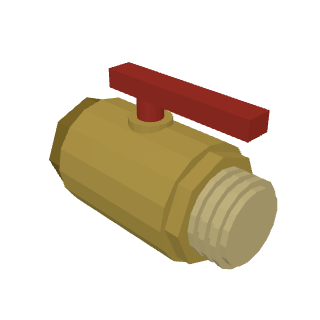
Master valve at the entry: shuts off the supply from the well to the whole house.
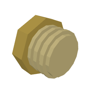
Reducing bush in the tee ahead of the drain valve and the gauge assembly.
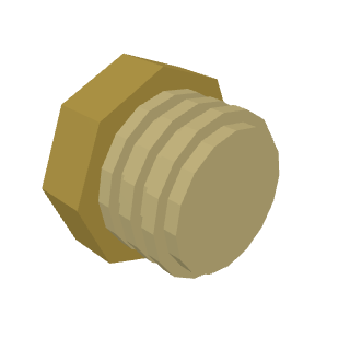
Bush for the 1/4" pressure gauge thread.
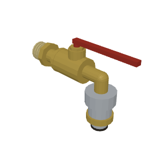
Garden valve with a quick coupling, tapped in before the filter — outdoor water bypasses the cartridge.
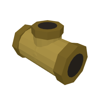
Brass tee at the entry: splits the main line and the garden/drain branch.
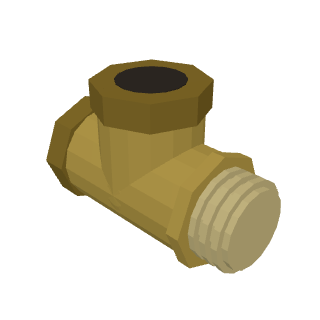
Tee on the garden branch: the garden valve and the system drain point.
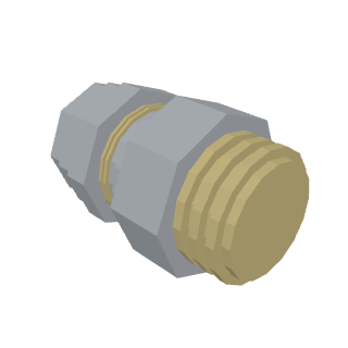
Compression coupling Ø20 × 3/4" for connecting the separate line to the water heater.
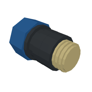
Transition from Ø32 HDPE to the one-inch thread of the master valve.
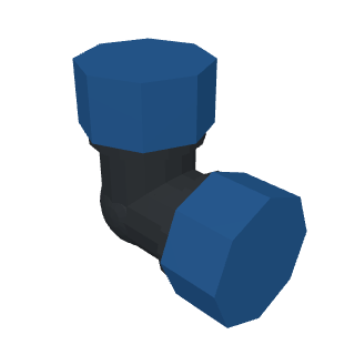
Turns of the HDPE pipe at the entry into the house before the change to polypropylene.
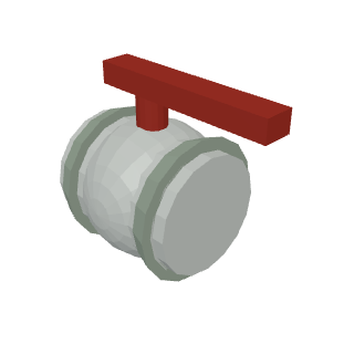
Three bypass valves: two either side of the filter, one on the leg that feeds water past the housing.
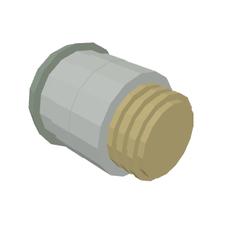
Adapter couplings Ø32 × 1" M for connecting the filter housing and joining to the brass.
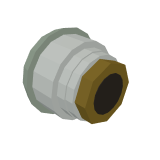
Transition from the Ø32 PPR main line to the 3/4" manifold inlet thread.
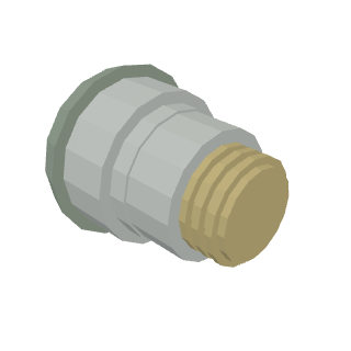
PPR-to-thread transition in the branch assembly after the filter.
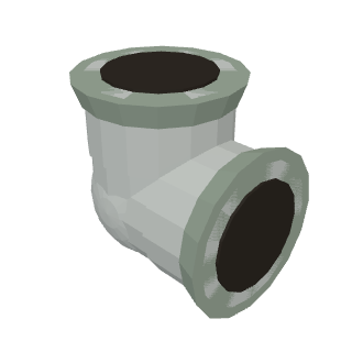
Turns of the polypropylene main line when passing the wall and running to the filter and the manifold.
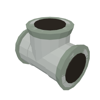
Tees for the bypass piping and for splitting the main line after the filter.
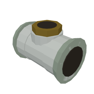
Tee with a threaded branch for the pressure gauge after the filter.
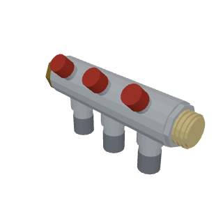
Cold water mini manifold with three Ø16 outlets on valves: kitchen, bathroom, second bathroom/laundry.
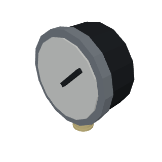
Pressure gauge after the filter: monitors house pressure and cartridge fouling.
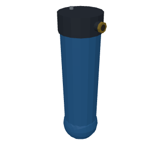
BB20 mains housing with a carbon cartridge, 1" connection on both sides.
Ø32 HDPE pipe on the entry section up to the change to polypropylene.
Ø32 PPR pipe from the entry to the manifold; the diameter is not reduced, to keep the housing's full bore.
How it was assembled, step by step
Entry from the well and the master valve
Bring the Ø32 HDPE pipe into the house and turn it with elbows towards the place where the board is mounted. Using the Ø32 × 1" adapter coupling, fit the brass master valve. Fix the section to the wall so that the valve is within reach and does not hang on the pipe.
Drain and garden take-off
After the master valve, assemble a brass unit from tees: one branch goes to the garden valve with a quick coupling, the second serves as the system drain point. Both branches sit before the filter so that garden water does not pass through the cartridge. Seal the threads and check them for tightness after start-up.
Change to polypropylene and the filter bypass
Change over to Ø32 PPR and keep this diameter right up to the manifold so as not to reduce the housing's one-inch connection. Mount the BB20 housing with the carbon cartridge on a bracket to the wall, leaving room underneath to remove the sump with the wrench. Pipe the housing with three PPR ball valves: two shut off the inlet and outlet, the third sits on the bypass leg.
Pressure gauge after the filter
On the filter outlet fit a tee with a threaded branch and screw in the 1/4" pressure gauge through the bushes. Turn the dial towards the walkway so the readings can be read without leaning. A growing pressure difference with an outlet open shows that the cartridge is due for replacement.
Water heater line and cold water manifold
Take a separate branch off the main line and run the water heater line through the Ø20 compression coupling. Bring the main branch onto the 3/4" mini manifold with three Ø16 outlets and valves. Label the branches: kitchen, bathroom, second bathroom with laundry — each one shuts off separately.
Pressure test and start-up
Close the valves on the branches, open the master valve and let water in, watching the gauge. Inspect all threaded joints and welded PPR joints, and nip up the brass if needed. Then open the branches one by one and flush each point until the water runs clean and free of air.
Video and animation
The video shows the assembly step by step: marking out and fixing to the wall, the change from HDPE to polypropylene, welding the Ø32 main line, mounting the BB20 housing and piping the bypass with three valves, tapping in the pressure gauge and connecting the mini manifold. There is also an animation of how the layout works: how water travels from the well through the master valve, part of it going out to the garden before the filter, passes through the carbon cartridge and splits to the water heater and three cold water branches, and how the flow switches to the bypass during a cartridge change.
Frequently asked questions
Why is a bypass needed at the filter?
A bypass is a leg with a valve that goes around the housing. By closing the valves on the filter inlet and outlet and opening the leg, you can remove the sump and change the cartridge without leaving the house without water. The bypass also helps if the cartridge is clogged and there is no replacement to hand.
Why is the main line kept at Ø32 up to the manifold?
The BB20 housing has a 1" connection. If you go down to a smaller diameter before or after it, that bottleneck will limit the flow when several points draw at once. That is why Ø32 PPR (the equivalent of one inch) is run from the entry to the manifold, and the reduction is made only on the Ø16 branches.
Why is the garden valve tapped in before the filter?
Garden watering does not need treatment, and outdoor consumption is high. Tapping in before the filter preserves the life of the carbon cartridge and avoids a pressure drop in the house caused by the housing's resistance.
What does the pressure gauge after the filter show?
It shows the pressure in the house on the clean side. Note the reading with a tap open right after fitting a new cartridge: when the pressure drops noticeably at the same draw, the cartridge is clogged and it is time to change it.
Is this layout suitable for a permanently occupied house?
The basic layout is put together for a holiday house of about 100 m² and a family of three. For permanent occupancy it is worth adding a mechanical cartridge ahead of the carbon in the configurator and, if needed, increasing the number of manifold branches for extra draw-off points.
How do you prepare the assembly for winter?
Close the master valve, open the drain valve and all draw-off points, remove the filter sump and drain the water from the housing. The water heater line must also be emptied, otherwise the remaining water will burst the joints when it freezes.